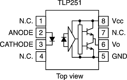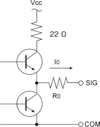

These are additional considerations to include in a fuller analysis not done here. We don't know if this is important, or not, just yet. Totem pole output, also known as a push-pull output, a type of electronic circuit The Totem Pole (Tasmania), a rock spire/sea stack in Tasmania, Australia. One of the first things to understand is the capability of the output, as that is what will be driving other inputs. To be used as totem pole digital output, the circuit is either in State H (Force High) or in State L (Force Low) according. Simulate this circuit – Schematic created using CircuitLab That drive capability guarantees each TTL output the capability to drive 10 TTL inputs with a guaranteed noise margin of 400mV or greater.Let me draw out the schematic using the editor (you should have done this, too.) TTL outputs will be 400mV or less when low (and sinking 16mA or less), and 2.4V or more when high (and sourcing 400uA or less). TTL inputs are defined as 'low' if they are less than or equal to 800mV and 'high' if they are greater than or equal to 2V. Without the collector resistor it would behave more like a few ohms (1.6K divided by the current gain of Qp). HIGH, LOW, or Types of logic gate outputs Totem poleOutput isHIGHorLOW.Open collectorOutput isoatingorLOW.Tri-stateoutputs combine Output can be HIGH, LOW, or oating Types of logic gate outputs Totem poleOutput isHIGHorLOW.Open collectorOutput isoatingorLOW. When Qs is 'off', the base of Qp is pulled to Vcc by Rc, so the effective pullup resistance is limited by the collector resistance Rcp - so it's about 120\$\Omega\$, meaning that for a 50pF load, the time constant is about 6ns. Totem pole outputs like this one use an active pullup, which is Qp, Rc and Rcp.

You can tie open-collector outputs together and use a pull-up resistor to create a wired AND gate. You can use diodes from each output with a pull-up or pull-down resistor, depending on the logic you want.

Figure 11.8.1 shows the circuit of a TTL NAND gate withopen. It's a component part of the (active) pullup circuit, but it's not a 'pullup resistor'. 2 If you tie two totem-pole outputs together, they will 'fight to the death' if they are set to different logic levels. This problem of TTLwith totem-pole output is overcome in TTL with open collectoroutput.

The primary purpose of the 120\$\Omega\$ resistor is to reduce the current spikes when the output switches (when Qo and Qp are both on simultaneously for a brief moment).


 0 kommentar(er)
